36+ physical and logical network diagram
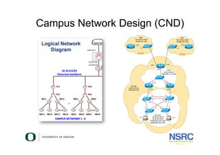
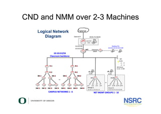
Logical network diagrams focus in on how traffic flows across the network IP addresses admin. Ad Templates Tools Symbols For Easy Network Diagrams.
How To Write A Winning Digital Marketing Strategy For Your Brand Quora
The two most common network diagrams youll come across are physical and logical.

. Below are the usual symbols used to present the usual instruments. The network topology shows templates that. On the other hand a logical network diagram indicates data and signal.
First draw a device that has the name ASW1. Draw a subnet pipe. About Press Copyright Contact us Creators Advertise Developers Terms Privacy Policy Safety How YouTube works Test new features Press Copyright Contact us Creators.
Usually in campus LAN topologies focusing at layer 2 at the switching layer some. Logical Design Logical design takes each piece of conceptual design and assigns it to a specific logical role within. A logical network interface or device is the software.
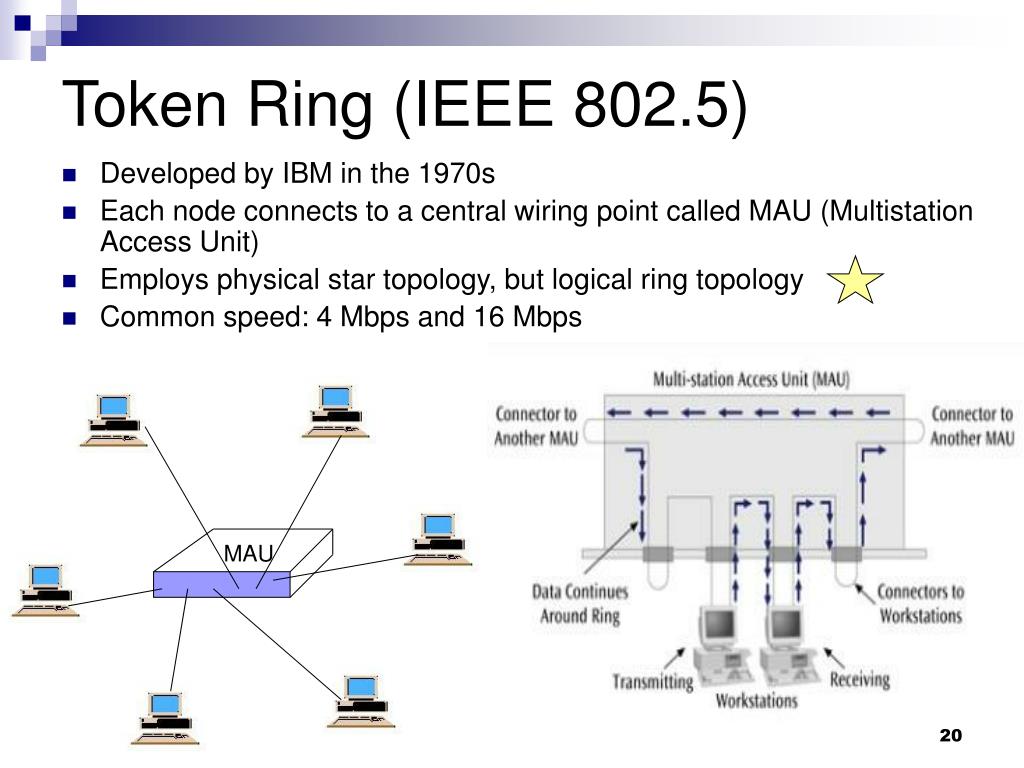
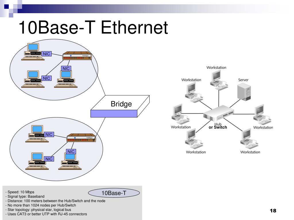
Physical topology describes the physical layout of the network while logical topology defines data flows on the physical layout. People often draw diagrams or pictures to. A physical network diagram indicates the connection of devices through cables or wireless connections.
ASW1 happens to be switch so well use the switch symbol. There are two types of topologies that are logical and physical. A physical network diagram depicts the network topology with the physical aspects like ports cables racks and more.
Symbols - the LND uses symbols that will represent the types of equipment included in the network. Network topology is the arrangement of components within a network describing a network diagrams physical and logical parts. The Difference Between Logical and Physical Network Design.
Give it the name In-mgmt VLAN-ID 250 and. The logical topology deals with network protocols that are used to control the data flow across the network. Therefore logical network diagrams typically show subnets including VLAN IDs masks and addresses.
Logical network topology illustrates at a higher level how data flows within a network. When documenting your networks both types of network diagrams are important and you can create both logical and physical network diagrams with netTerrain. A logical network diagram describes the way information flows through a network.
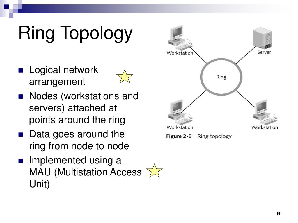
Ppt Lan Topologies Access Methods Powerpoint Presentation Free Download Id 774041

Logical Network Diagram Physical Network Diagram Network Monitor Networking Topology
Virtualisation For Network Testing Staff Training
2
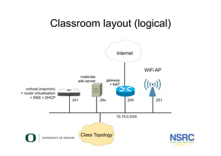
Virtualisation For Network Testing Staff Training
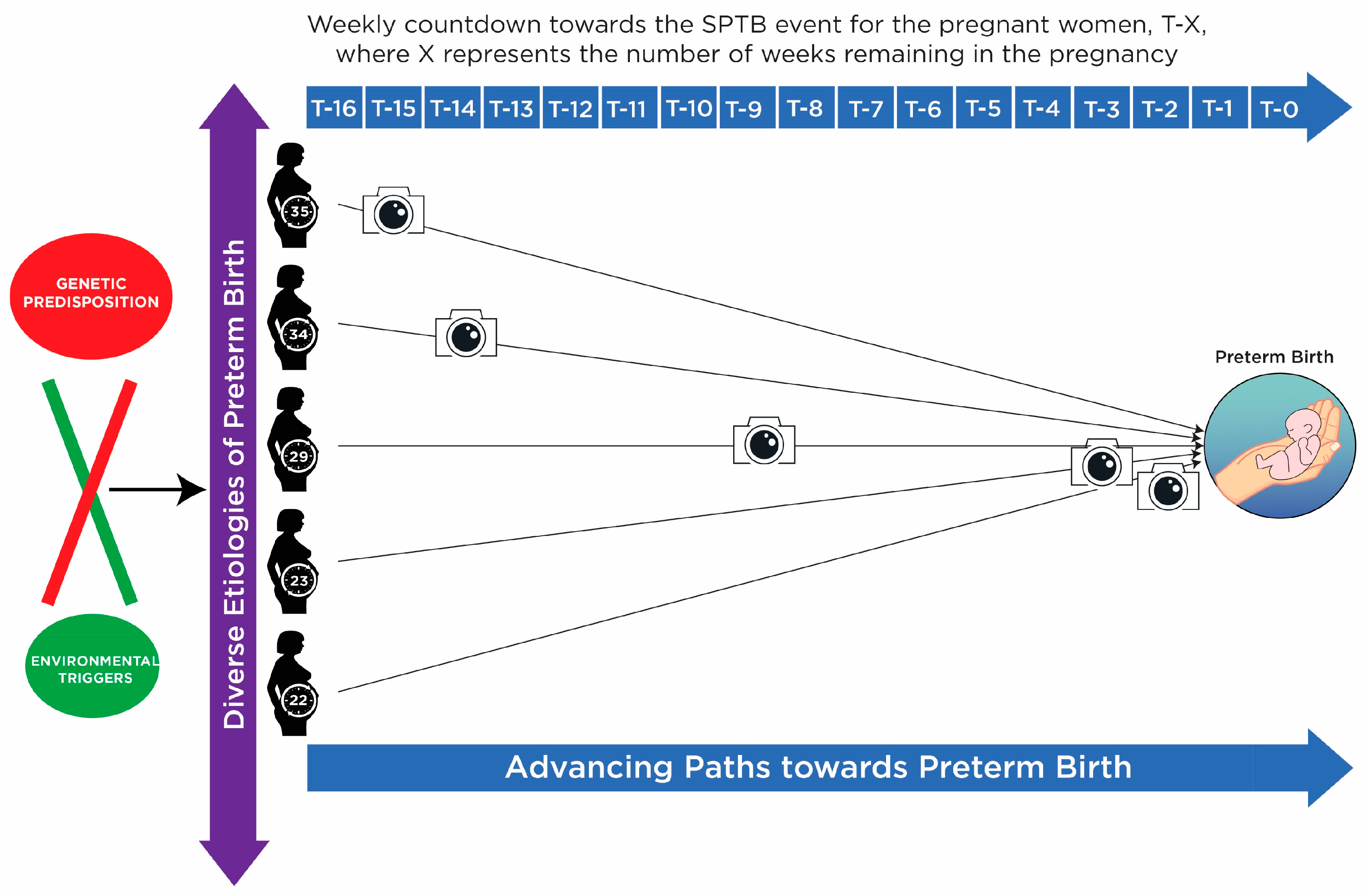
Metabolites Free Full Text Screening For Preterm Birth Potential For A Metabolomics Biomarker Panel Html
Virtualisation For Network Testing Staff Training
Ppt Lan Topologies Access Methods Powerpoint Presentation Free Download Id 774041
Virtualisation For Network Testing Staff Training

Physical Vs Logical Topology Networking Infographic Topology Computer History
2
Ppt Lan Topologies Access Methods Powerpoint Presentation Free Download Id 774041

Physical Network Design Process Define The Logical Architecture How Many Nodes Are On The Network What Types Of Nodes Physics Topology Networking

Design Elements Logical Network Diagram Computer Network Networking Network Architecture
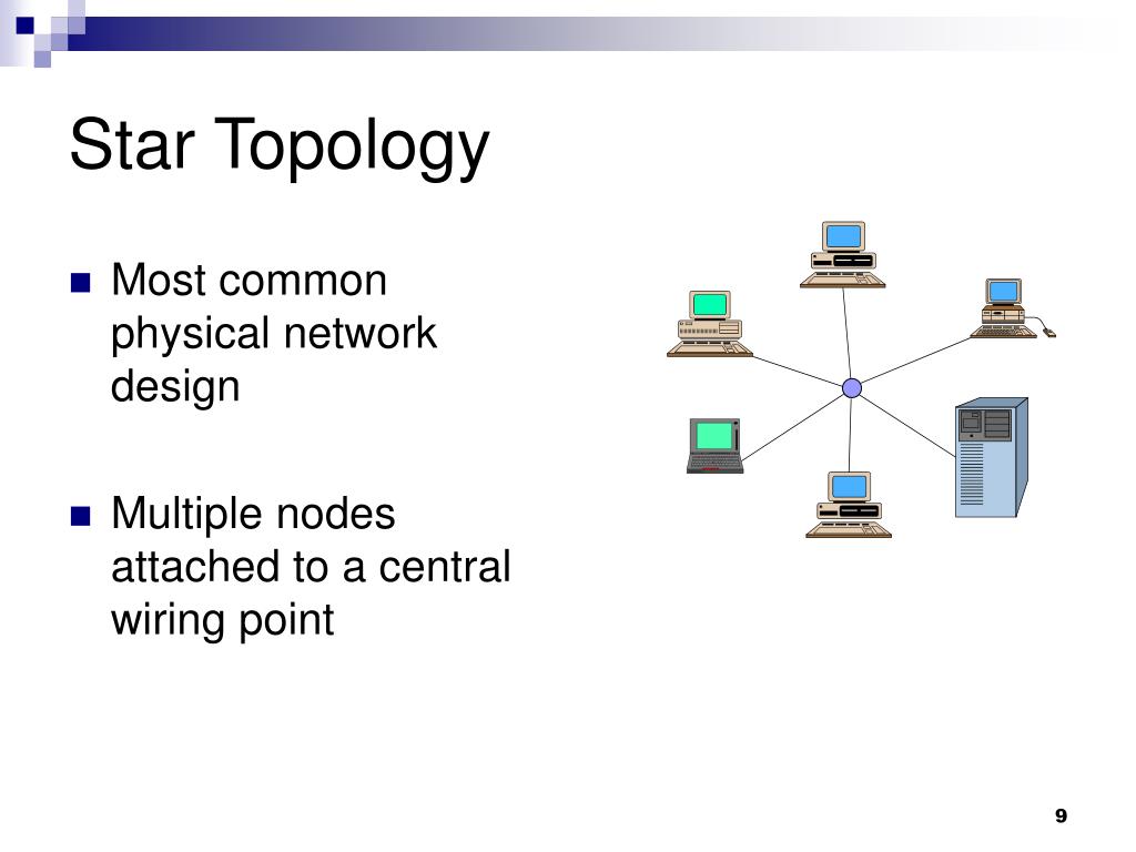
Ppt Lan Topologies Access Methods Powerpoint Presentation Free Download Id 774041
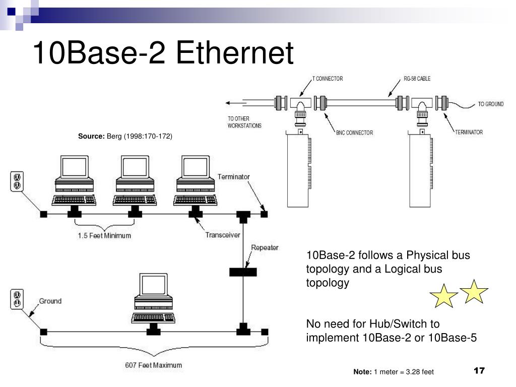
Ppt Lan Topologies Access Methods Powerpoint Presentation Free Download Id 774041

Virtualisation For Network Testing Staff Training